15th of March, 2026
If you thought the previous chapter was abstract, you’re going to love this one. Bear with me as I explain some of these foundational things as they will make everything which follows much easier to understand. The next chapter will show us how these abstract concepts are used in the real-world (in hardware/physical constructions).
Computers use electrical signals to perform computations. These electrical signals can be either on or off. The binary system we saw in the previous chapters maps to this system of electrical signals. Another way to view these signals is as boolean (or truth) values. When electrical current is flowing and the signal is on, we can view as the true state. The opposite case, when there is no electrical current and the signal is off can be seen as a false state. All operations a computer performs can be mapped down to boolean logic. Logic which uses exclusively true and false values.
Boolean logic uses three basic operations. These operations are AND, OR and NOT. The AND operation takes two values, \(x\) and \(y\), and returns true if both \(x\) and \(y\) are true. If either or both values are false, the operation return false. Explaining this in text can be confusing and complex, and this is where truth tables can help us. These tables show the input values for a given operation, across all possible state combinations, with the resulting outcome. Let’s take a look at the truth table for the AND operation:
| \(x\) | \(y\) | Result |
|---|---|---|
| 0 | 0 | 0 |
| 1 | 0 | 0 |
| 0 | 1 | 0 |
| 1 | 1 | 1 |
This table shows us that the AND operation will only return true (denoted by 1) if both input values are true. The OR operation will return true if either or both of the input values are true. This results in the following truth table:
| \(x\) | \(y\) | Result |
|---|---|---|
| 0 | 0 | 0 |
| 1 | 0 | 1 |
| 0 | 1 | 1 |
| 1 | 1 | 1 |
Finally, the NOT operation flips the value of its input. If you give it a true value, it will return false, and vice-versa. This is reflected in its truth table:
| \(x\) | Result |
|---|---|
| 0 | 1 |
| 1 | 0 |
The three basic operations together are functionally complete. This means that using these three operations we can create any other logical operation. This section will cover one such operation, the XOR (exclusive OR). This operation returns true only if exclusively one of the input values is true. If both values are true the XOR will return false. How would you construct this operation using the three operations above? Take a second to think.
We can use the following combination of all three operations to construct the XOR: (\(x\) AND NOT \(y\)) OR (\(y\) AND NOT \(x\))
Now, you might be thinking, what do I do with this knowledge (as I was during my university class on logic)? How is this boolean logic relevant for computers and whatever my partner does at work? Let me explain. Logical operations can be used to perform any operation we want. In the realm of computers everything is a logical operation (as it is just 1’s and 0’s, true and false). As an example, let’s sum two numbers using logical operations!
Logical operations can be represented in physical form using logic gates. Logic gates are commonly constructed using transistors (these will be explained in the next chapter) and make up the Central Processing Unit (CPU). Multiple logic gates are combined into a circuit.
The previous chapter explains how the summing of two binary values works. We can represent this process using a circuit consisting of two types of logic gates. The process of addition requires comparing three bits. The first two bits are the bits of the values we are summing up. The third bit is the ‘carry bit’, which is the value carried by the previous addition. We can represent this operation using the circuit below:
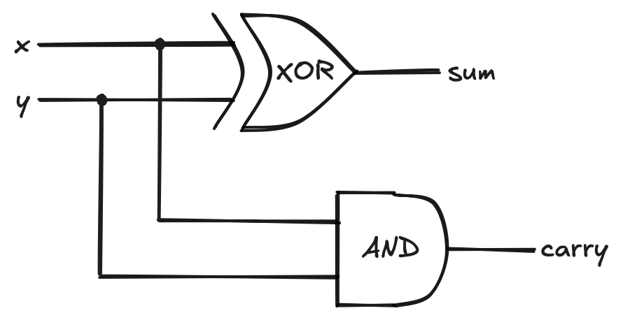
This circuit is called a half-adder circuit and has the following associated truth table:
| \(x\) | \(y\) | \(sum\) | \(carry\) |
|---|---|---|---|
| 0 | 0 | 0 | 0 |
| 1 | 0 | 1 | 0 |
| 0 | 1 | 1 | 0 |
| 1 | 1 | 0 | 1 |
While this circuit works for summing two bits, it does not check for any incoming carry value from a previous addition. The more complex full-adder circuit allows for adding three bits together, one of which is the carry value from a previous addition. The full-adder circuit is constructed as follows:
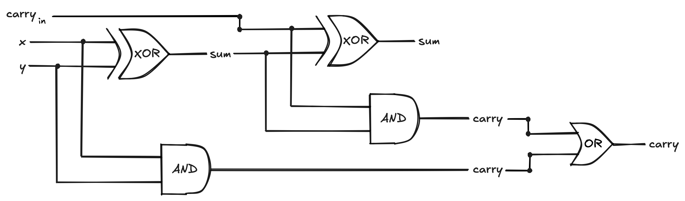
Which has the following truth table:
| \(x\) | \(y\) | \(carry_{in}\) | \(sum\) | \(carry\) |
|---|---|---|---|---|
| 0 | 0 | 0 | 0 | 0 |
| 1 | 0 | 0 | 1 | 0 |
| 0 | 1 | 0 | 1 | 0 |
| 1 | 1 | 0 | 0 | 1 |
| 0 | 0 | 1 | 1 | 0 |
| 1 | 0 | 1 | 0 | 1 |
| 0 | 1 | 1 | 0 | 1 |
| 1 | 1 | 1 | 1 | 1 |
Try and run through the circuit for two or three input combinations to get a feeling for how this circuit works! The beauty of this circuit is that we can link \(n\) of these circuits after each other to perform the addition of an \(n\) bit binary number. The first circuit in the chain would be a half-adder, as initially there will be no carry value, followed by \(n - 1\) full-adder circuits. These would be linked up as follows:
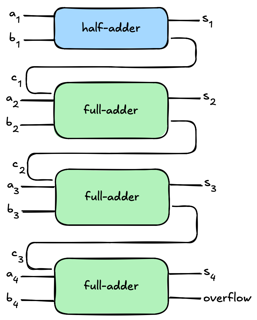
This circuit can add two four-but numbers. Each circuit gets the input bits at its index, as well as the carry value from the previous addition. The final result is a four-bit number given by \(s_1\) to \(s_4\). An example calculation of this would be the following, where we add the numbers 0110 (6) and 0011 (3):
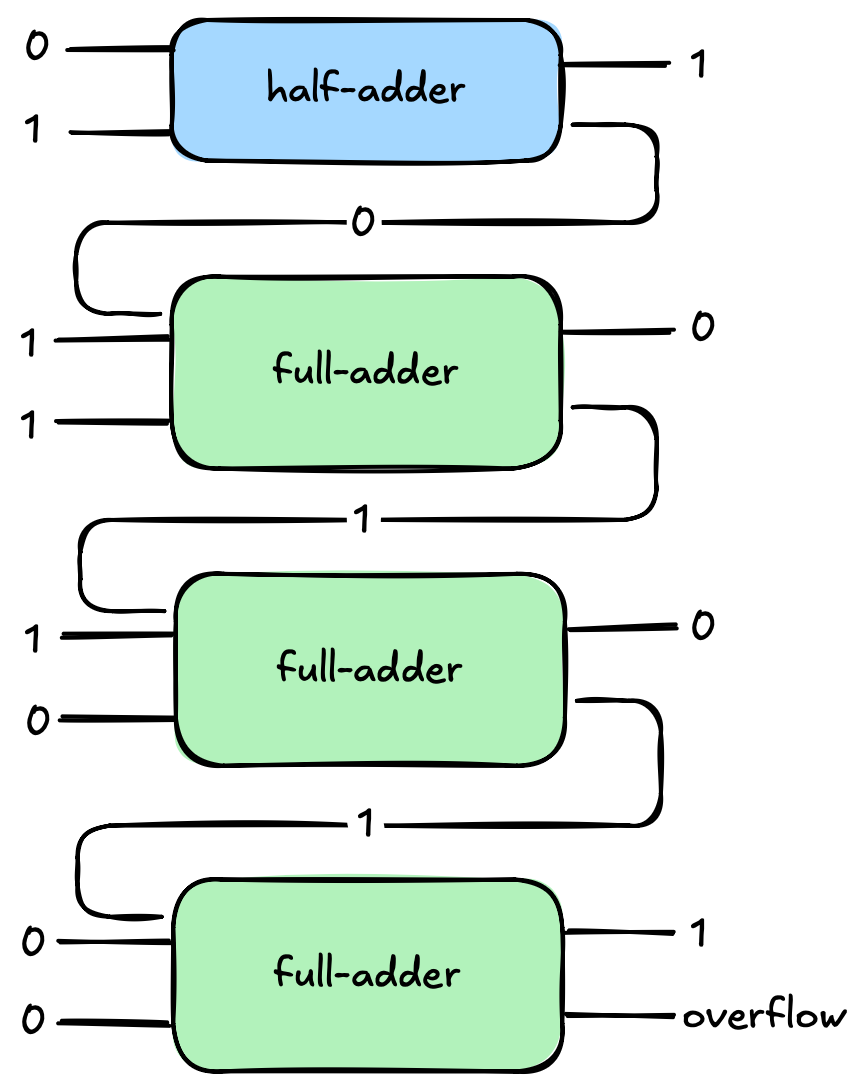
Which, correctly, results in 1001 (9). A small reminder, in case you forgot as I did while writing this, we add the bits going from right to left (same way we do this with the decimal system), and when retrieving the final sum we set the bits from left to right as well.
In This chapter we started with simple boolean logic, saw how this logic was used in logic gates, how logic gates linked together form circuits, and how these circuits can perform operations like addition. In the next chapter we will look into what parts a computer is made of, including the actual physical pieces which are used to build these logic gates and circuits!